This circuit can be broken down into four parts
i)
Voltage Regulator circuit
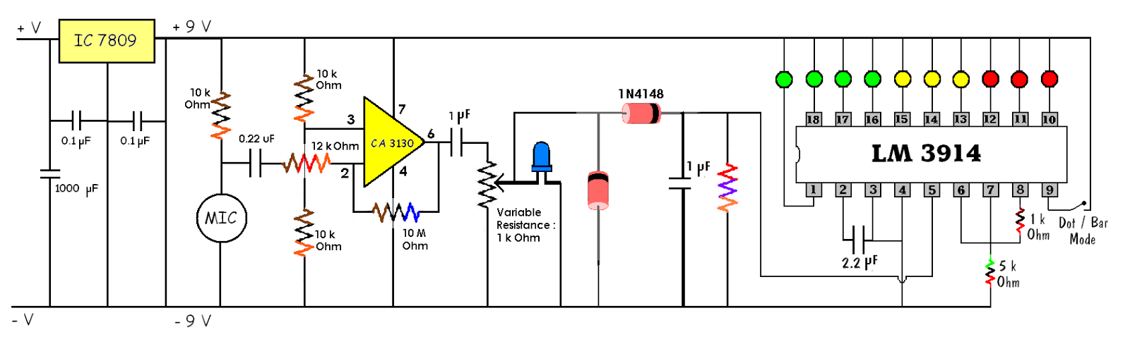
1 . Voltage Regulator Circuit :
A
voltage regulator is used to get a regulated power supply of a specific voltage
. Here we use IC 7809 . The last two
digits of the IC specifies the value of regulated voltage ( output ) . Since 09
is the last two digits of this IC , we get a regulated power supply of 9 volts
 It is a 3-pin IC . The IC is placed such that its butt points
towards us . Then the three pins of the IC are Input , Ground and Output
respectively.
It is a 3-pin IC . The IC is placed such that its butt points
towards us . Then the three pins of the IC are Input , Ground and Output
respectively.
To the first pin , any higher voltage ( upto 35 volts) can be
given .
2
. Microphone and Amplifier circuit :
 The sound intensity sensor is built around a condenser microphone.
OPAMP IC CA3130 and associated
components OPAMP is configured as a high
gain inverting amplifier. The voltage supply to IC CA3130 at its non inverting
Pin 3 is divided to half by two 10 K Ohm resistors, which is also used as the
reference voltage. Resistor R1(10 k Ohm ) determines the sensitivity of the
condenser microphone.
The microphone picks up sound vibrations and converts them
into the corresponding electric pulses, which are fed to the inverting input of
IC 2 (Pin 2) via capacitor C4 ( 0.22 uF) and resistor R2 ( 12 k Ohm ).
Capacitor C4 ( 0.22 uF) blocks any DC entering the op-amp, Since it may affect
the functioning of the op-amp. The output of IC 2 is connected to the inverting
input through resistor R5 (10 M) for negative feed back. Since the input
impedance of IC2 is very high even a small current can activate the op-amp.
The sound intensity sensor is built around a condenser microphone.
OPAMP IC CA3130 and associated
components OPAMP is configured as a high
gain inverting amplifier. The voltage supply to IC CA3130 at its non inverting
Pin 3 is divided to half by two 10 K Ohm resistors, which is also used as the
reference voltage. Resistor R1(10 k Ohm ) determines the sensitivity of the
condenser microphone.
The microphone picks up sound vibrations and converts them
into the corresponding electric pulses, which are fed to the inverting input of
IC 2 (Pin 2) via capacitor C4 ( 0.22 uF) and resistor R2 ( 12 k Ohm ).
Capacitor C4 ( 0.22 uF) blocks any DC entering the op-amp, Since it may affect
the functioning of the op-amp. The output of IC 2 is connected to the inverting
input through resistor R5 (10 M) for negative feed back. Since the input
impedance of IC2 is very high even a small current can activate the op-amp.
Since we have used a 10 k Ohm resistor ( R1) , the microphone
picks up sound only after 40 decibels.
3
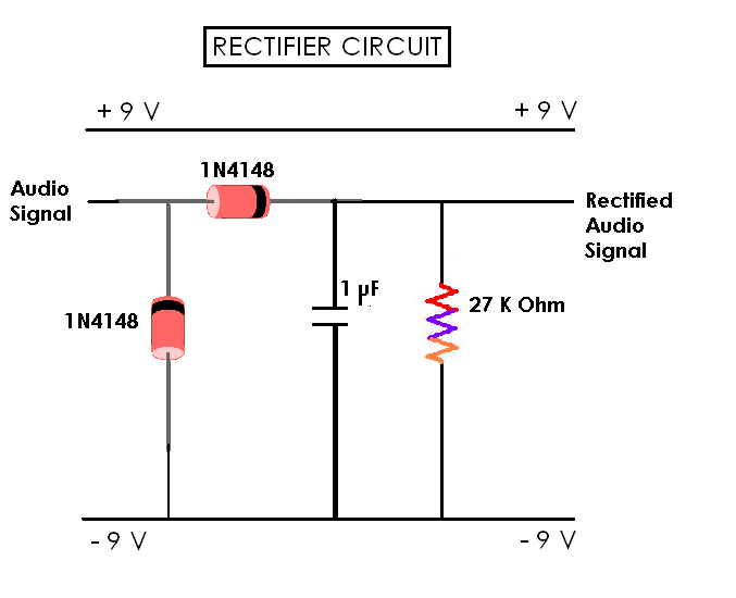
. Rectifier circuit :
 The output of IC2 is given to preset VR1 via capacitor C5,
which is used to control the volume. Capacitor C5 ( 4.7 uF) blocks DC, allowing
only AC to pass through a variable resistor (preset ) VR 1 ( 1 k Ohm ). The AC
signals from the wiper of VR 1 are fed to a diode pump comprising diodes D1
& D2 ( 1 N4148 ) . The diode pump rectifies the AC and maintains it at the
output level of IC2. Capacitor C6 ( 1 uF) acts as a reservoir capacitor for DC
and resistor R6 ( 27 k Ohm ) provides the path for its discharge.
The output of IC2 is given to preset VR1 via capacitor C5,
which is used to control the volume. Capacitor C5 ( 4.7 uF) blocks DC, allowing
only AC to pass through a variable resistor (preset ) VR 1 ( 1 k Ohm ). The AC
signals from the wiper of VR 1 are fed to a diode pump comprising diodes D1
& D2 ( 1 N4148 ) . The diode pump rectifies the AC and maintains it at the
output level of IC2. Capacitor C6 ( 1 uF) acts as a reservoir capacitor for DC
and resistor R6 ( 27 k Ohm ) provides the path for its discharge.
4
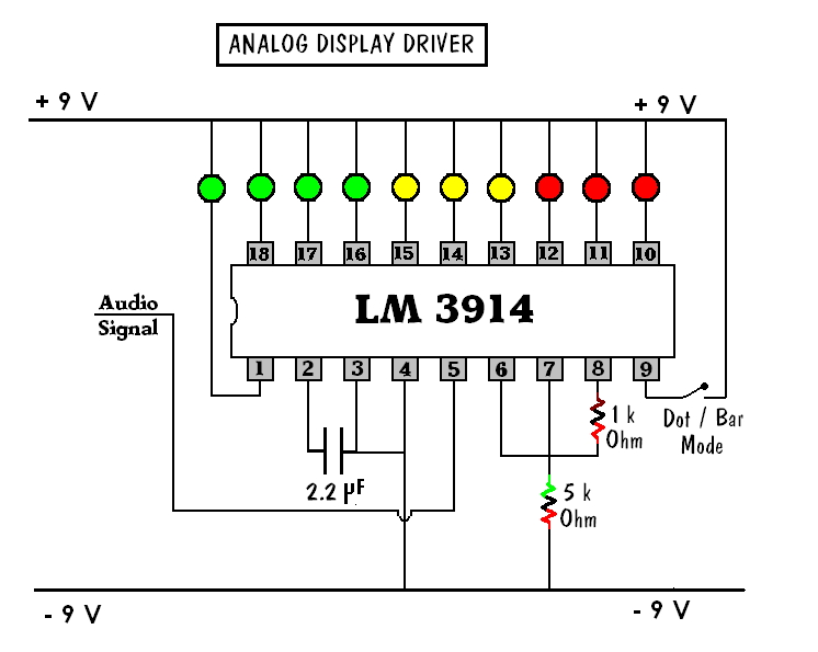
. Analog Display Driver circuit :
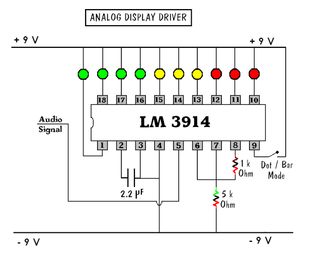
The display circuit is built around monolithic IC LM 3914
(IC3), which senses the analogue voltage and drives ten LEDs to provide a
logarithmic analogue display. Current through the LEDs is regulated by the
internal resistor of IC LM3914, eliminating the need for external resistors.
The built in low bias input buffer of IC3 accepts signals down to ground
potential and drives ten individual comparators inside IC3. The outputs of IC3
go low in a descending order from 18 to 10 as the input voltage increases.
Each LED connected to the output to IC3 represents the sound
level of 3 dB, so when all the 10 LEDs glow it means the sound level intensity
is 30 dB.


The completed Project :
Photos of my project :


